How to Choose the Right Threaded Inserts?
Choosing the right Threaded Inserts starts with the material around the joint. An insert that works well in aluminum may loosen in softwood or crack a thin plastic panel. The details matter. Identify the base material, its thickness, and the loads the connection must carry. A small bracket holding a sensor has different demands from a fastener supporting repeated vibration.
Then compare insert type, thread size, grip range, and installation method. For example, a blind rivet nut can create a threaded fixing in sheet metal when access is limited to one side. A heat-set insert may suit a molded plastic part, while a screw-in insert can work in wood. Check the manufacturer’s specifications for pull-out strength, recommended hole size, installation torque, and compatible tool. Corrosion resistance also matters in damp or outdoor settings; the wrong finish can become a weak point.
There is no universal winner. A catalog chart helps, but it cannot show every real-world fit. Even experienced buyers can overlook wall thickness or installation access. A test on a sample part can reveal spinning, cracking, or poor thread engagement before production begins. If the joint is safety-critical or carries changing loads, have the design reviewed by a qualified engineer and verify it under expected conditions. The right choice is usually the one that fits the material, load, and assembly process—not simply the strongest insert on paper.
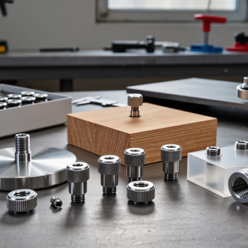
Define the Substrate and Loads with ASTM D1761 Wood-Fastener Testing
Choosing a threaded insert starts with the wood, not the catalog rating. Record the species, density, moisture condition, and grain direction. A soft pine block and a dense hardwood board can respond very differently to the same insert. Small details matter. Note the pilot-hole diameter, drilling method, installation depth, and distance from edges. A hole that is slightly oversized can weaken the result.
ASTM D1761 provides test methods for evaluating mechanical fasteners in wood, including withdrawal and lateral resistance. It can help structure a comparison, but an insert needs a suitable test setup and clearly documented installation procedure. Measure the force needed to pull the insert from the substrate, and assess how it performs under sideways loading when that reflects actual use. Keep the wood dimensions and conditioning consistent across specimens. Test multiple samples; one unusually strong piece of timber proves little.
Loads in service may combine tension, shear, vibration, and repeated assembly. The standard test results are useful evidence, not a guaranteed field rating for every wood species or joint. That distinction is easy to overlook. I would also record failures plainly: stripped wood, insert rotation, or metal damage tell different stories. If the test fixture or procedure differs from the intended application, say so. Imperfect data can still guide selection, provided its limits stay visible.
Compare Press-Fit, Heat-Set, Molded-In, and Helical Insert Designs
Press-fit inserts suit quick assembly in rigid thermoplastics. Their knurls bite into a drilled hole, but thin walls can split and plastics can creep under sustained load. Heat-set inserts use a heated tip to soften the surrounding plastic; after cooling, knurls resist rotation and pullout. Control temperature, dwell time, and insertion depth. A tilted insert is hard to forgive.
Molded-in inserts are placed before resin enters the mold, creating strong mechanical engagement without a later installation step. They suit higher-volume parts, but require tooling and careful control of resin flow around the insert. Helical inserts repair or reinforce internal threads in metal parts; they need enough parent material and a correctly sized tapped hole. They are not a direct substitute for plastic inserts. Check the load path. ISO 898-1 specifies a minimum tensile strength of 800 MPa for property class 8.8 steel bolts; that figure describes the bolt, not the insert or its host material. NASA’s Fastener Design Manual, RP-1228, also stresses evaluating preload and joint behavior rather than relying on fastener strength alone. In practice, test the full assembly under the expected pullout, torque, temperature, and vibration conditions. One detail often gets missed: the “strongest” design may still fail if the surrounding plastic cracks.
Match Thread Size and Pitch: M6 × 1.0 mm or #10-32 TPI
Choosing a threaded insert starts with the screw it must accept, not a visual guess. M6 × 1.0 mm means a nominal 6 mm diameter and 1.0 mm between adjacent thread peaks. A #10-32 thread has a nominal diameter of about 4.83 mm and 32 threads per inch, or roughly 0.794 mm between threads. They can look similar at a glance. They are not interchangeable.
Keep metric and inch measurements separate while checking specifications. A pitch gauge can help distinguish 1.0 mm pitch from 32 TPI; a ruler usually cannot. Check the insert’s internal thread marking against the screw drawing or a known sample screw. Then start the screw by hand. If it binds after a turn or two, stop rather than forcing it. Forced engagement can damage the threads and make later inspection harder.
The pitch is only part of the match. Confirm the nominal diameter, thread form, and required fit, especially when replacing an insert in an existing part. This detail is easy to overlook. I would not rely on a close-looking screw as proof; drawings can be incomplete, and a quick gauge check may catch a mismatch before installation.
Select Insert Material and Check ISO 3506 Stainless-Steel Grades
Choose an insert material for the actual service conditions, not just the parts list. A damp indoor assembly may need different corrosion resistance from a fitting exposed to salt spray or cleaning chemicals. ISO 3506 identifies stainless-steel groups and property classes for corrosion-resistant fasteners. A2 is commonly used for general environments, while A4 is often selected where chlorides are present. These labels are not a complete performance guarantee.
Check the insert’s technical data for its stainless-steel designation and property class. Classes such as 50, 70, and 80 relate to mechanical properties; they do not rank corrosion resistance. Confirm that the stated ISO 3506 requirements apply to the insert itself, since product specifications can vary. Also consider the parent material, installation method, and expected load. A harder insert in a soft aluminum component, for example, may still fail if the surrounding material strips. Small details matter.
It is easy to overfocus on the grade. I would also check whether the insert and mating fastener could seize or corrode together, especially in wet service. If the documentation is unclear, ask the supplier for the material certificate and test conditions. A confident label alone is not enough.
Verify Pilot-Hole Size, Installation Torque, and Pull-Out Ratings in Datasheets
How to Choose the Right Threaded Inserts?
Verify the pilot-hole diameter against the insert datasheet and the actual workpiece. A nominal drawing may not reflect drill wander, coatings, or a softer-than-expected substrate. Too small a hole can raise installation force or split the material; too large a hole can weaken retention. Small differences matter. Check the specified drill size with a gauge, and note the material, thickness, and hole-making method. I would not assume one pilot size suits every alloy or plastic.
Use the listed installation torque as a limit, not a target to exceed. NASA’s Fastener Design Manual, RP-1228, reports about ±25% accuracy for torque-controlled fastener preload. That figure describes bolted joints, not every insert installation, but it shows why torque alone can be imprecise. Use the insert maker’s stated method and a calibrated tool where practical. Then check pull-out ratings under matching conditions: substrate, embedment, edge distance, and loading direction. ASTM D7332 provides a test method for fastener pull-through in fiber-reinforced polymer composites; its results should not be treated as universal insert ratings. Ask how the published value was tested. A datasheet rarely captures every field condition, and that uncertainty deserves attention.
How to Choose the Right Threaded Inserts? - Verify Pilot-Hole Size, Installation Torque, and Pull-Out Ratings in Datasheets
Use the insert manufacturer’s datasheet for product-specific limits. Pilot-hole diameter, installation torque, and pull-out strength vary with insert design, material, dimensions, and installation method; there is no universal value for a given thread size.
| Selection dimension | What to verify in the datasheet | How to use the information | Example or unit |
|---|---|---|---|
| Internal thread | Nominal thread diameter, pitch, thread tolerance, and compatible screw specification. | Match the insert thread to the fastener and the required load. Do not use the thread size to infer the pilot-hole size. | Common metric coarse threads: M3 × 0.5, M4 × 0.7, M5 × 0.8, M6 × 1.0. |
| Insert type and host material | Insert style and approved substrate, such as a specified plastic, wood, or metal; note any material grade or temperature limitations. | Select an insert designed for the actual substrate and installation process. Heat-set, press-in, molded-in, and metal thread-repair inserts are not interchangeable. | Record the substrate grade and insert installation method before comparing ratings. |
| Pilot-hole diameter | Recommended hole diameter, tolerance, depth, and whether the hole should be drilled, molded, or tapped. | Use the value specified for the exact insert and substrate. A hole that is too large can reduce retention; one that is too small can damage the workpiece or prevent correct seating. | Diameter in mm or in; depth in mm or in. Do not substitute a generic drill chart. |
| Installation conditions | Installation tool, alignment requirements, temperature (if applicable), insertion depth, and any cooling or curing instructions. | Follow the procedure for the insert type. Keep the insert aligned and avoid over-insertion, substrate cracking, or damage to internal threads. | Record temperature in °C or °F where heat installation is specified. |
| Installation torque | Whether a torque limit is specified, the relevant installation step, and the test or assembly conditions associated with the value. | Use a torque value only for the specified insert and process. Do not treat screw-tightening torque as insert-installation torque; they are different operations. | Torque is commonly stated in N·m or lbf·in. If the datasheet gives no limit, do not invent one. |
| Pull-out rating | Pull-out force, test method, substrate, hole preparation, installation procedure, specimen geometry, and failure criterion. | Compare ratings only when test conditions are comparable. A pull-out result is not automatically a safe working load; apply the design factor and requirements for the application. | Force is commonly reported in N or kN. Check whether the value is typical, minimum, or an allowable design value. |
| Edge distance and wall thickness | Minimum edge distance, required wall thickness, and recommended spacing between inserts, if stated. | Check these dimensions against the part geometry to reduce the risk of splitting, cracking, or local material failure. | Dimensions are typically given in mm or in and depend on the substrate and insert design. |
| Final verification | Current datasheet revision, specified test conditions, and any application-specific qualification requirements. | Confirm the selected insert in representative material and geometry when the joint is safety-critical or the production process differs from the datasheet test setup. | Document the insert specification, hole size, installation process, and validation results. |
Article Source:
Get a quote
Get a quote
Read More
Accept AllReject AllCustomise
Privacy Overview
| Cookie | Duration | Description |
|---|---|---|
| cookielawinfo-checkbox-advertisement | 1 year | Set by the GDPR Cookie Consent plugin, this cookie records the user consent for the cookies in the "Advertisement" category. |
| cookielawinfo-checkbox-analytics | 11 months | This cookie is set by GDPR Cookie Consent plugin. The cookie is used to store the user consent for the cookies in the category "Analytics". |
| cookielawinfo-checkbox-functional | 11 months | The cookie is set by GDPR cookie consent to record the user consent for the cookies in the category "Functional". |
| cookielawinfo-checkbox-necessary | 11 months | This cookie is set by GDPR Cookie Consent plugin. The cookies is used to store the user consent for the cookies in the category "Necessary". |
| cookielawinfo-checkbox-others | 11 months | This cookie is set by GDPR Cookie Consent plugin. The cookie is used to store the user consent for the cookies in the category "Other. |
| cookielawinfo-checkbox-performance | 11 months | This cookie is set by GDPR Cookie Consent plugin. The cookie is used to store the user consent for the cookies in the category "Performance". |
| CookieLawInfoConsent | 1 year | CookieYes sets this cookie to record the default button state of the corresponding category and the status of CCPA. It works only in coordination with the primary cookie. |
| viewed_cookie_policy | 11 months | The cookie is set by the GDPR Cookie Consent plugin and is used to store whether or not user has consented to the use of cookies. It does not store any personal data. |
| Cookie | Duration | Description |
|---|---|---|
| _cs_c | 1 year 1 month | The cookie is used by Content Square to save the user consent to be tracked. |
| Cookie | Duration | Description |
|---|---|---|
| _cs_id | 1 year 17 days 20 hours 13 minutes | This cookie is used to store the ContentSquare's user identifier ID. This is a persistent cookie and expires after 13 months. |
| _cs_s | 1 hour | This cookie is used to store the number of page's viewed by a visitor within the session for ContentSquare's solution. |
| _ga | 1 year 1 month 4 days | Google Analytics sets this cookie to calculate visitor, session and campaign data and track site usage for the site's analytics report. The cookie stores information anonymously and assigns a randomly generated number to recognise unique visitors. |
| _ga_* | 1 year 1 month 4 days | Google Analytics sets this cookie to store and count page views. |
| _gcl_au | 3 months | Google Tag Manager sets the cookie to experiment advertisement efficiency of websites using their services. |
| Cookie | Duration | Description |
|---|---|---|
| test_cookie | 15 minutes | doubleclick.net sets this cookie to determine if the user's browser supports cookies. |
| Cookie | Duration | Description |
|---|---|---|
| _cs_root-domain | session | Description is currently not available. |
| _cs_same_site | session | Description is currently not available. |